I've also snapped some pics of several sketches and prints I've drawn up, and nearly all of those are Taig mods, upgrades, or related parts for my tools and equipment. I think I've finally figured out how to take decent pics with this camera (starting about halfway through the pics in this post, or a couple days ago), too, so you should be able to make out the details that have been so blurry in previous pics from here on.
An Enco order (well, most of it) arrived today as well as the "T" slot cross slide casting kit for the mini lathe, so there are some pics of it here, too. The biggest accomplishment over the past few days has been making an extension for the threading attachment on my Sherline 4400 lathe. With it, I no longer need to remove the motor to single-point threads on it; I didn't say I'd use the motor with the Sherline aluminum gears, I've just gotten to the point to where I hate removing it to use the threading attachment and replacing it once I'm through. This set-up allows for gearing identical to the Sherline instructions-no need to remember to use the "E" and "F" gears that would normally be used for left-hand threads when cutting standard right-hand threads; it's basically just a mirror image of the way Joe Martin intended it to be used now with a long aluminum extension that allows the hand crank to clear the rear of the motor.
There's more pics of other things too, but I'll have to comment on those later as I'm running out of time...
Here they are:

I used what I had lying around for the hand crank extension-this was a piece of 6061 I used for test cuts after the initial headstock alignment after using "Rollie's Dad's Method" with a precision ground and hardened 0.7500" steel bar in the Sherline 3.125" 3-jaw chuck, using my Starrett #25-511 indicator (0.0001" resolution, 0-5-0 dial reading, and 0.200" travel). Wanted to use steel for this piece, but I found this faster in my messy stock pile.

A few more pics of work on the crank extension...

Another...

Exciting, huh? Don't worry-the better stuff's coming up...

Test fitting the new ground QCTP body-I'm not going to harden this because I plan to use the A2Z aluminum holders until I build some larger and more robust versions. The first ones will probably be made from 12L14, but there's about twelve feet of 1.5x1.25" 316 (not quite sure on this-it may be 304) stainless at school that I want to use for the more simple holders I plan to use frequently, mostly for aesthetic purposes and corrosion resistance, polished to a mirror finish of course. The above pic shows how it will currently sit on the OEM Sieg compound if mounted through the centered hole at the base of the bore and post in the OEM tool post mount, but I plan to modify the mounting hole in the compound so the tool post will sit with the entire dovetail on both sides completely protruding from the side and front of the compound to allow the use of taller holders and large-shank tooling (3/8" shank tools are the maximum that can be used with the A2Z holders and post mounted in the stock configuration; all of my carbide insert tooling is 1/2" shank so the A2Z holders will need to sit lower on the new post and will most likely need longer height-adjusting screws). See the pic below for a visual interpretation:

This is how I want the QCTP to mount so I can use 1/2" shank tools in the stock A2Z holders with longer height-adjustment screws. With custom holders designed for them, I'll be able to use 3/4" or even 1" shank tools this way.

Closer view, but the camera settings still weren't right. If you can see the pencil-drawn rectangular box surrounding the bore centered in the dovetail, that's the area that will be milled out to accomodate either brass or 2024 aluminum locking pads secured to the eccentric-actuated pegs by counterbored SHCS (10-32 or possibly 1/4-20). No rush on this-I want to build the new cross slide first and PERFECT the new 14" between centers bed casting kit purchased from LMS when it was on sale. I'll have a perfect example of a precision lathe with full contact on all parts of all sliding surfaces capable of "holding it's own" against any top quality lathe "out of the box;" I'm no expert in machine tool construction, filing/scraping/lapping sliding surfaces, or in any similar field, but I'm confident that I can fit these parts better than any of the ya-hoos on Sieg's assembly line. Massive mods are in the near future for this machine...

Drilling, boring, and reaming the bore that will ride over the spindle-I had to use the wrong reamer because of the 3/8" chuck capacity, but it fits nearly snug...

Another view? Duplicate pic? You decide...

My latest class project-for a grade-that I've nearly completed. Only a few minor alterations need to be made before polishing to ensure I get the best grade possible.

I'll get more pics after these are fully completed; I would classify each knurled diameter as "very good," which isn't quite as nice as a Starrett knurl but MUCH better than some of the other commercially available tools I own and have seen.

Slight differences in a couple of places that will be corrected soon.

Starting on my next school project: a grinding or toolmaker's vise. 4" OD round bar with excessive scale was turned on my favorite lathe there, the 17x84" American Pacemaker. If you look at the pic of swarf below, you can tell that my feed rate was too low on the roughing passes, but chips this size don't worry me. If they didn't break at all, I'd definitely increase the feed, but I like nice finishes whenever possible-we're all human and make mistakes (some of us on a very frequent basis!), so if I miscalculate and end up with a roughing pass that brings the OD to size, I still usually end up with a finish that needs little sanding before polishing.

Feed too slow-the speed's probably not as close as it could've been either judging from the lack of a dark blue hue in this pile of swarf.

When faced to length, all the roughing passes produced perfect chips and backing the tool back to the edge from center removed no additional material. However, my finish pass was a little shy on the depth of cut with the same speed and feed (and the saddle locked to the bed, of course), so I ended up with a finish that wasn't what I hoped for. More time polishing in this area should remove the majority of flaws, but I had hoped to get it as nice as those roughing passes.
S-L-O-W feed-long and stringy chips but an excellent finish with an insert that has a larger nose radius.

A beautiful turned finish-it's a shame that it'll all be faced away to form the rectangular blank of the vise body. :(

After setting this up I realized that I needed at least two ground wrench flats to turn this reamer (which was the correct one for this job), but it was too late to run my bench grinder to add them so I used another 9/16" reamer that actually measured a bit more than I liked, but it works.

It's a good thing I bought the 4400 lathe, huh?

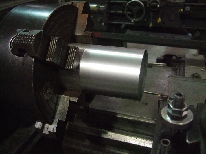
Test fitting the extension

Another blurry test-fit pic

Less blurry test fit pic

Preparing to mill the additional features needed for this component.


Something missing? It took some time, but I figured out how to remove this hard stop/X axis gib lock screw retaining pin on my own, since nobody on the Taigtools Yahoo group wanted to share any thoughts, tips, tricks, or ideas on removing this without destroying it.

Threading attachment, hand crank and extension, and motor installed. The coupling for the threading attachment was engaged to very proper set-up and operation for left- and right-hand threading and to check resistance when the spindle turns CCW (viewing the chuck from the back of the headstock) while the motor and drive belt were still attached. Seems to work okay, but the drive belt should be slackened and/or disengaged for various reasons when using this set-up.

More pics of the same mod-a few different views and camera settings coming up...


I know-that set screw retaining the extension to the spindle is too long. It was borrowed from my QCTP holder hardware parts until I pick up one that's better sized for this job.


Hmm-nobody's asked what the three 1/2-20 hex head bolts on each side of the headstock will be used for yet...

OMG-removing this pin was a nightmare! I even put a couple of small scratches in my Taig's table in the process (oops!).

The bore for the pin is a through hole-the Y axis leadscrew is exposed with the pin removed. I wouldn't recommend operating the mill without the pin or a cover and some alternate means of locking the X axis gib.

Finally removed!

Close-up showing how badly I damaged the pin in the process.

I've designed a stronger X-axis gib locking system that doesn't require any pin in the bore left from the hard stop pin, but will use a pressed sleeve, tapered nuts, and expanding mandrel-style cover for the bore that will also serve as a self-aligning and retaining arbor for the head of the X-axis digital scale that will be connected to my Shumatech DRO-350.

Beautiful stress-relieved cross slide casting-the link to purchase this quality part is located in a previous post (and the distributor, Mr. Andrew Lofquist, is a wonderful person to deal with), but I'll post it again if I get any comments on this post about it.

This is a typical amount of chips/swarf that I produce at school in less than two hours. I think my Taig would fall apart before it ever produced this many correctly shaped and colored chips in its stock configuration.

Closer view of today's pile-I started on this Bridgeport late this morning, a bit after nine, and it was 11:30 by the time I'd dumped this and the pile of chips that couldn't fit into the dust pan in the garbage can, so with one 15-minute break and clean up time I'd estimate this pile was produced in about one hour and 45 minutes.

Some sketches of mine-I probably shouldn't share much of this info because I often come up with good ideas and alternate means of accomplishing various tasks-some of which could possibly be patented or at least used in my future business ventures, but it's hard enough to read my writing in person as small as it is, so feel free to plagiarize my work for personal use if you can read it; business or commercial use will require my written permission and of course compensation.

I won't give out any details on these, so just carefully look at each of them, comparing them all to each other and you may have a general idea of how my Taig will look once these mods and upgrades are completed.

I'll tell you what the sketch above is: this was the rough idea for constructing my own spindle tram/square gage. I've since purchased another new Starrett #25-511 indicator to use with my existing one of the same model in this. CNC equipment at school will do all the machining-I just draw it up, check it thoroughly (backplot, simulation, and manually scanning G-code), load the parts in the machine and press a few buttons (occasionally override the speed or feed rates) and the hard work's done to extremely tight tolerances, freeing me up to concentrate on other things. I'll have to press the stepped shaft in place (sketch in lower right corner) and calibrate the indicators to a "master," which in this case would be a single reference edge on a 2J series BP trammed to within 0.0001" over the larger 6" center distance of the indicator retaining bores and even less between the smaller 3" center distance I plan to use for verifying and modifying the YZ alignment with an out-of-square disk (more on that later-I briefly mentioned this concept in my last reply to Ken Cline on the Taigtools Yahoo group if you'd like to read up on my thoughts and ideas for it there in the mean time).

Prints for a matched set of spacers that will raise the High-Tech Systems, LLC 1/2x4x18" matrix/tooling/modular work holding plate I should receive soon 0.5000" above the aluminum table of my Taig.

These are secret until I've built them-you probably can't read my hand writing, so I'm not too worried about anybody copying or stealing this idea...

How do you know what the feed rate you're running while hand-cranking is fairly accurately (especially for beginners)? I calculated the chart above to convert IPM feed rates into both RPM and RPS (rotations per minute and rotations per second, respectively) for a few different inch per minute rates. The math is easy, but I'm a nerd-if you can use this chart but need different feed rates and don't want to guess by interpolation (and can't figure out the math to calculate it on your own), feel free to contact me through the comments on the bottom of this post or at rxforspeed@yahoo.com and I'll explain the formulae.

Mostly Z-axis way cover ideas-more on this in the near future...

Bending details for a single way cover section (a minimum of four sections is needed for both the bottom and the top of the Z axis, as well as multiple sections in different styles for the front and rear of the Y axis/saddle and the underside of the X axis/table to all but eliminate swarf and contaminents from the ways and leadscrews of each axis of this machine; all in preparation for small time/small scale CNC production work).

QCTP ideas-the bottom version was an attempted copy of one belonging to Jerry Glickstein (homemade) and another individuals I ran across on a website that I can't currently remember, but will credit as soon as I can find it again.

Two-axis grinder tool rest attachment idea-still in the R&D phase.

An attempt at drawing the supports I'd mentioned for the Z column of my Taig, but the tiny 8x11 graph paper wouldn't easily let me sketch this to any true scale. Another attempt will be made soon and posted ASAP.

1/2HP 90VDC 56C frame spindle motor mounting ideas-newer versions are drawn in the latest version of Esprit but I haven't had the chance to convert them to a file that can be viewed on a typical PC (without CAD or CAM software).

I love this cross slide and can't wait to start milling and grinding on it!

Another view...

Bottom view-Mr. Lofquist sells some quality casting kits for DIY'ers like us, check him out at http://www.statecollegecentral.com/metallathe/index.html . His prices are well worth it for the quality of his kits and castings, and he offers many lathe components and tools that are designed for South Bend, Logan, or Atlas/Craftsman lathes but can be altered for other machines...
That's it for tonight-more soon...