You know, I think I'd be much better off if I'd complete less projects at a time before picking up more. I'll put a project on hold while waiting for the best tool for the job, the optimal material in a size that won't produce much waste, or more frequently waiting on hardware to be located and purchased, then I'll sometimes start back on an existing project that's been on hold AND a completely new one. The reason the first project in this cycle gets put on hold is jotted down on a list, which is usually filed away where it won't be seen when needed. By the time I get the chance to order the tool, get the material, or acquire the bolt that's held me up, the same cycle has repeated itself exponentially and the newest items needed for the latest projects are more fresh in my mind than the original. I'm going to try to change that and pick only two at any one time (well, two for the home shop, one required for school, and another larger or non-free-machining project of my own to work on in class) to complete before moving on to any others.
Much of my time is spent designing parts and coming up with reasons to justify modifying something. I'll spend most of my free time during the day drawing up ideas; though many are refined and improved upon until I'm satisfied, a number of them never make it any farther. If I were to quit drawing projects today, I'm sure that by only using my prior sketches I would still be able to occupy every minute of my spare time and most of the rest of my time for the remainder of my life, provided I live to retirement age (still over 30 years away)!
The first pic is a sample of one of my sketches (three projects alone on this page, only one will start soon). The next pic is a page from a boring head print by Stephen Campbell, hosted with permission on Dean Williams' website. A PDF copy of the boring head prints can be found here:
Stephen Campbell's Boring Head, Dwg 1210-001
and Dean Williams' site here:
Dean's Machining Projects
Remaining pictures are progress of my boring head (note that I did salvage that chunk of unmachined 2024 from the part just turned) and a bit beefier QCTP for the mini lathe I've started on in class within the last couple of days. It's based upon A2Z's prints (they can be found by clicking on the pic of the QCTP set from A2Z CNC's store), but an additional 0.275" have been added per side and another 0.375" added to the height while the post has been milled from 2" square HRS. In the dyed form in the pics, an additional 0.020" have been kept on all six sides for final squaring in the surface grinder. I'm sure an oiled finish would suffice for this, but I try to add extra details and go the extra mile when I can. There may be polished stainless tool holders following this, but A2Z pieces (and T.S. Engineering QCTP tool holders) will fit it too.
Although I tried to set it up properly and spent over an hour today with my manual bead-roller/flanger/shear, I just didn't have the time to set up a guide fence for shearing the way cover material precisely. Two more projects added to the list: a stand with more support for the above mentioned machine and a small sheetmetal brake to bend the aluminum flashing material I bought to build the way covers from. The brake won't have to be very rigid as the flashing material is only 0.009" thick and shouldn't bend more than 3" or so of it at a time, but I will have a good deal of bends to make and would like to have some precise stops for bending to close tolerances. More on this later.
Anyway, here's the pics:
I'm a lefty, BTW-just in case you're wondering if the pic is inverted because the spiraled binding is on the right hand side. It's not, I just use my notepads backwards as I write so I don't continually rub my wrist on the the binding.
Big chuck for a little lathe, huh? The carbide insert tool post was left on the lathe when I reinstalled this chuck with the part remaining in it for concentricity, it was actually cut with HSS tooling.
M22 x 1.5 internal threads-I don't trust any lathes in class set up for metric threading, so all that is done on my Sherline. Though I have taps in this size, I wanted a better fit and perfect concentricity of these threads to the body. The black part screwed into the boring head body is a Taig 3/4-16 to ER16 collet adapter; I use it for test fitting single pointed threads for spindle mounted accessories without having to remove them from the lathe to check them on the mill. It would also double as an ER16 collet holder for my Sherline, but I'd rather make one if I needed to mill anything on it to ensure the taper and bore the collet would ride in is aligned with the lathe's centerline.
I didn't-though I wanted to make more progress on this piece, I just couldn't waste that much aluminum. That's 2" diameter material, and it's not exactly growing on trees around this workshop...
The new QCTP for the HF 7x mini lathe-still unfinished, of course.
Rear view: all six sides of this part will soon see the surface grinder.
Bandsaws are good, I'll use that sliver of aluminum for something.
Stock Taig headstock with spindle, bearings, spacer, and "faux gib" removed.
Stock Taig 3/4-16 spindle.
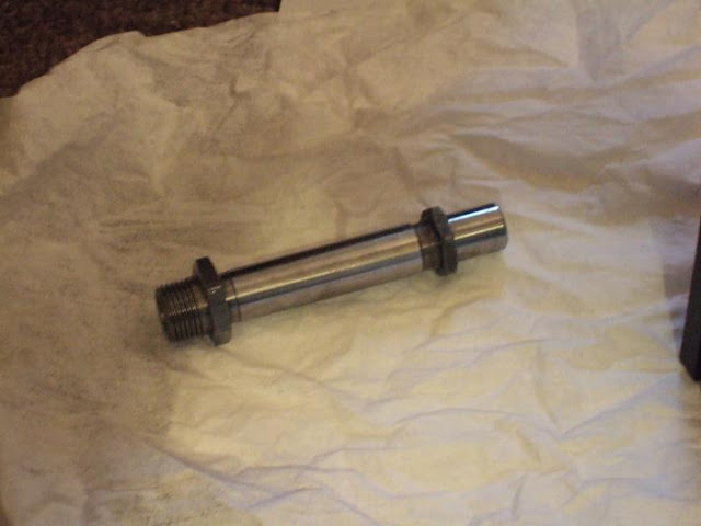
New parts that I've had for over a month. What else did I need to finish this headstock?
Back to work now-I'll post again soon...


No comments:
Post a Comment